Fin Can Section

The threaded rod is clamped to the workbench to hold it in place while cutting.
 by a light cut with the hacksaw. Then the tape measure is removed and the threaded rod is cut.")
The 3/8-16 threaded rod for the fin can section is marked at 27.25in (692mm) by a light cut with the hacksaw. Then the tape measure is removed and the threaded rod is cut.

The threaded rod for all of the subassemblies was cut to length with a hacksaw.

The locations for the top and bottom holes of the fins were marked my scoring a cross with the sharp points on the calipers.

Here is the resulting mark on the fin. Note that a line in both the X and Y directions have been scored, but one of the lines is not very visible due to the light.

The top and bottom holes on the fins were started using a countersink bit.

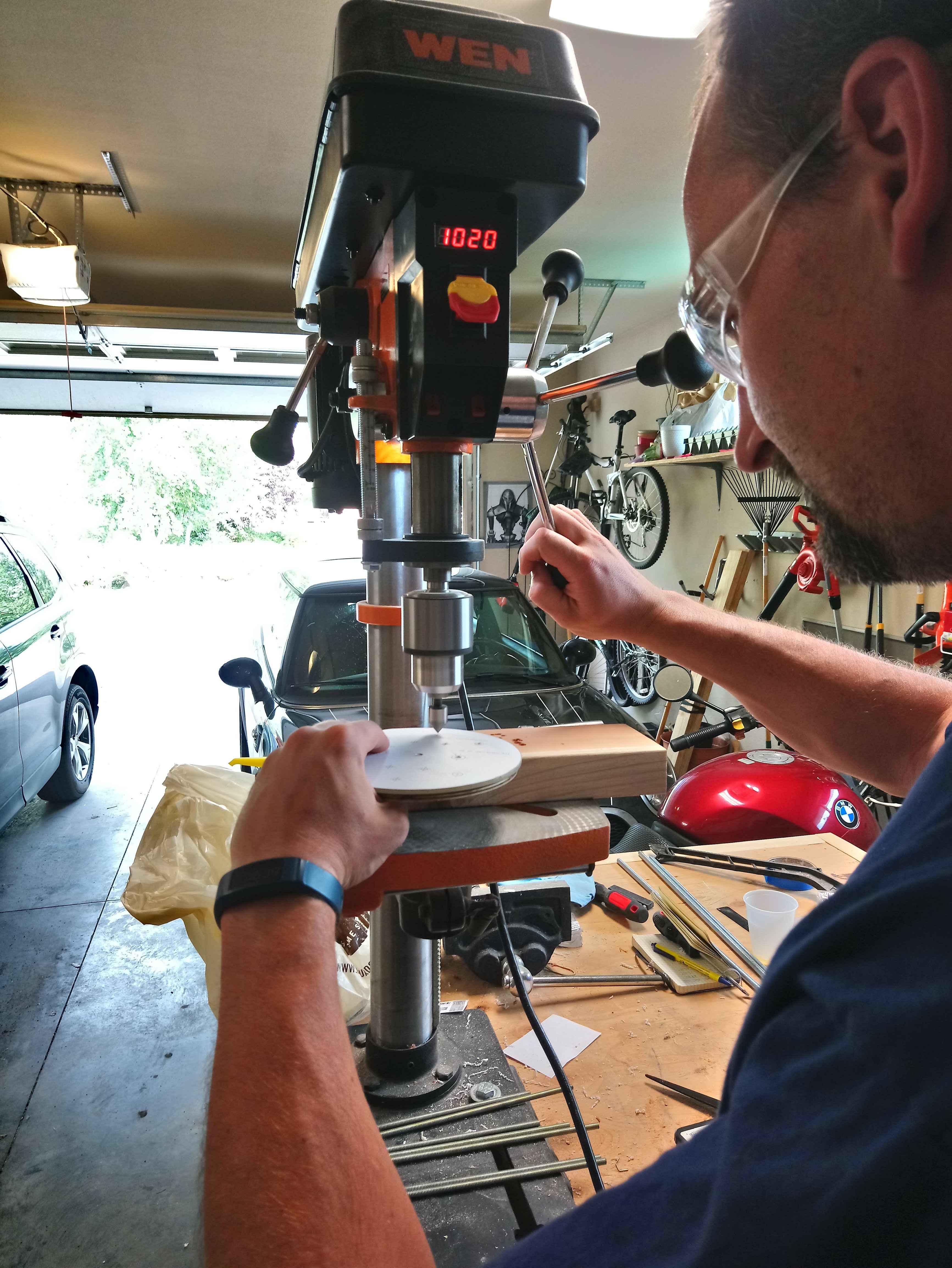
After the holes locations were started, the holes were drilled through the fin.

After the top and bottom holes were drilled in the fins, the fin mounts were test fit to ensure that the holes lined up. Everything went together without a problem

The thrust plate was installed onto the bottom tabs fin mounts and the AeroPack motor retainer was screwed in place.

The motor mount tube was installed into the assembly to test the fit inside the thrust plate.

To mark the remaining holes on the fins, a transfer punch was used. This punch was close to the same diameter as the holes in the fin mounts which centered the punch in the correct position. The punch was then struck with a hammer to mark the hole locations.

The resulting marks on the fins from the transfer punch.

This photo shows what the fin mounts look like when one fin is removed.

The remaining holes in the fins were started with a countersink bit after their locations were marked with the transfer punch.

Drilling the holes in the fins.

All of the holes drilled into the fins.

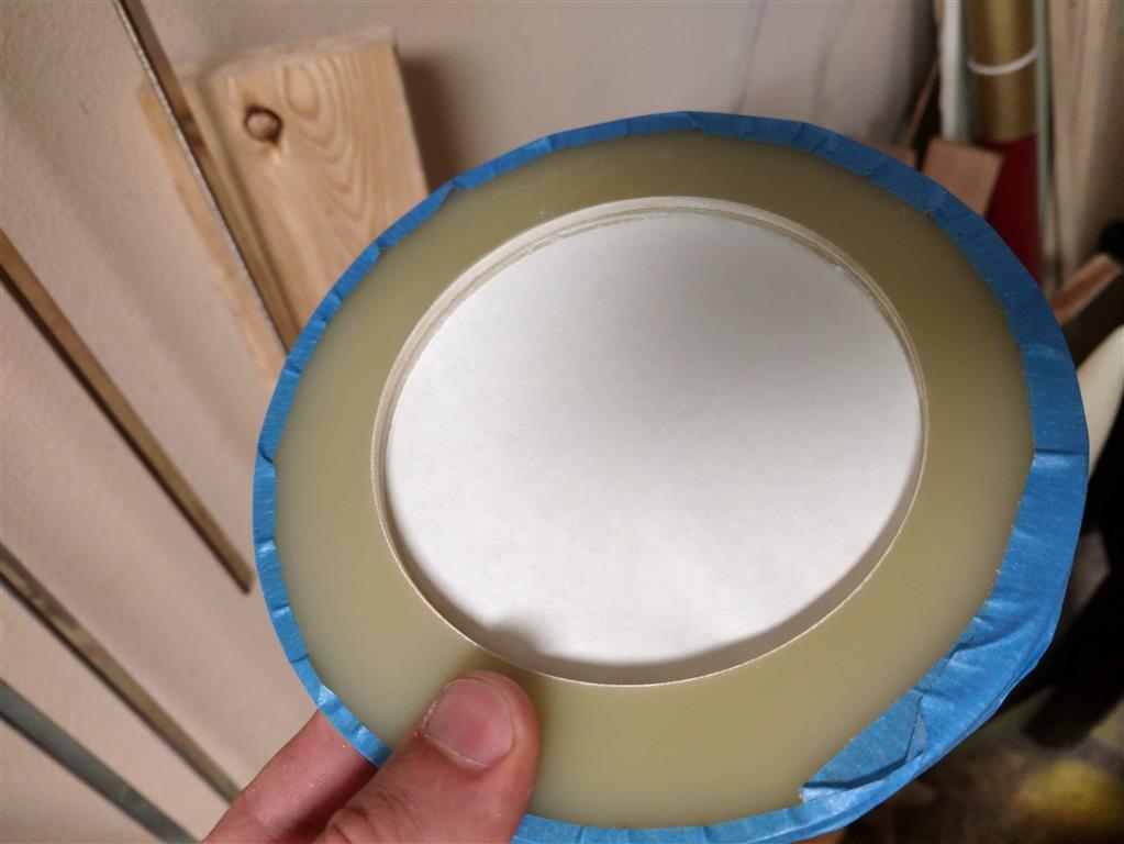
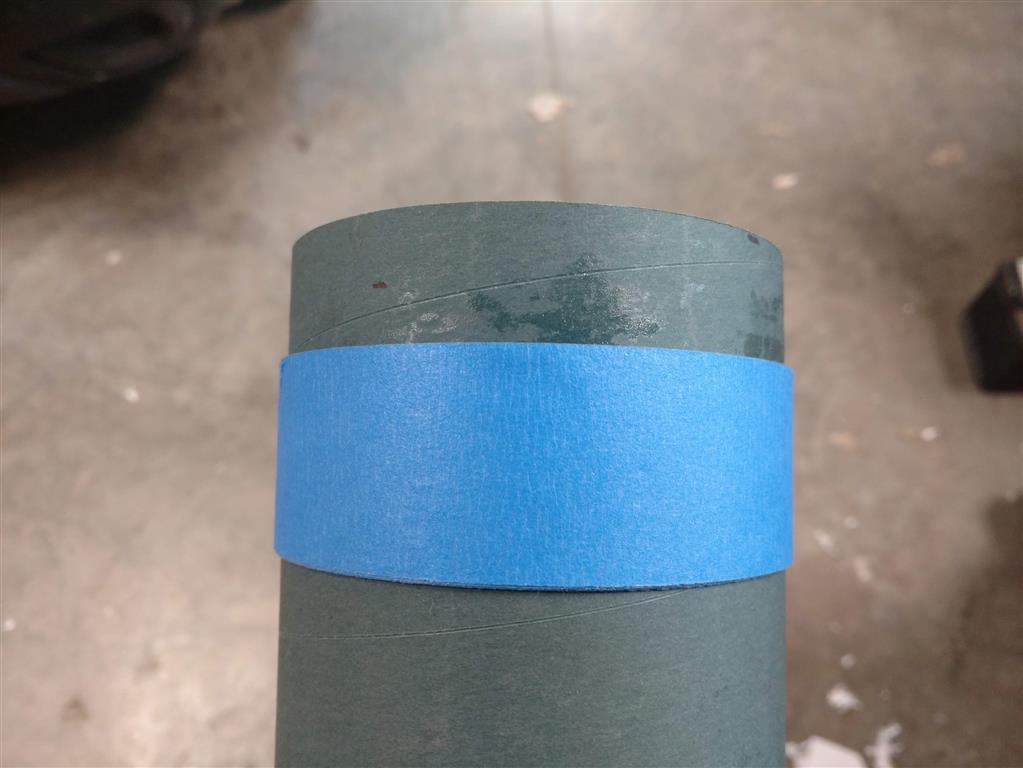
The calipers were locked at 1.50in and then were used to score the polycarbonate tube that will be used as the window for the camera. Many score marks were made around the entire outside diameter.

The polycarbonate tube was cut with the miter saw with a fine-tooth blade. Since the tube was larger in diameter than the saw could cut at one time, many small cuts were made around the tube. This limited the deflection of the tube due to internal stresses during the cut.

This is the window just after it was cut. Small notches are present on the cut side from where the internal stress of the polycarbonate caused the tube to deflect into the kerf while it was cut.

The inside of the wooden centering rings were slightly too small to fit over the motor mount tube. The Dremel tool with a sanding drum was used to remove a very small amount of wood from the ID.

After the inside diameter was correct, the template was glued onto one surface and a scrap piece of motor mount tube was slide inside the centering rings to keep them concentric.

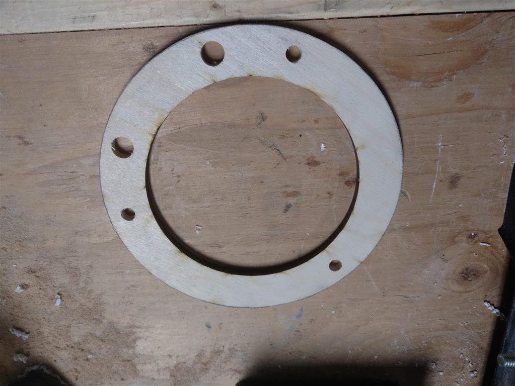
The wooden central centering rings after the holes were drilled.

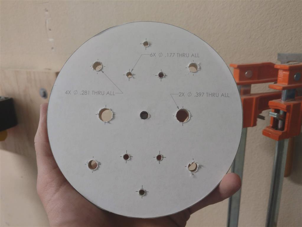
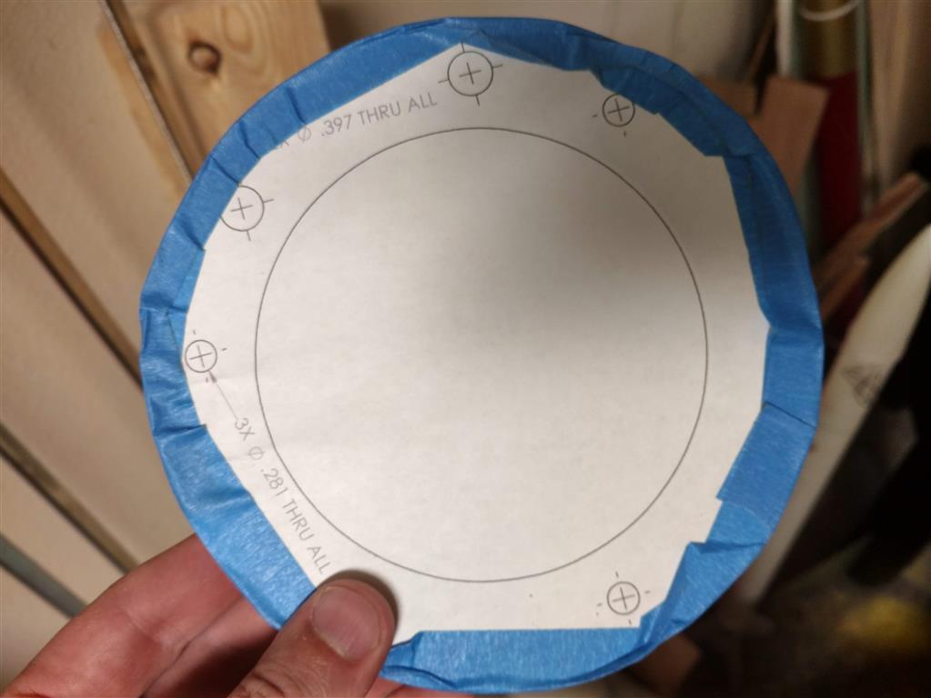
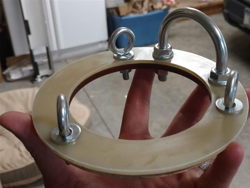
The part drawing for the fiberglass centering rings was printed out at 1:1 scale. It was then cut out and glued to the fiberglass centering ring with a Elmer's glue stick as used as a template for where to drill the holes for the threaded rods and U-bolt.

The holes in the central fiberglass centering rings were started using a countersink bit. These centering rings also had a small scrap of motor mount tube installed in the inside diameter to hold them concentric.

After all the holes were started, they were drilled through.

After the holes were all drilled, the template was removed. This was done first by just pulling off most of the paper...

Any remaining bits of paper were scrapped off with a small putty knife.

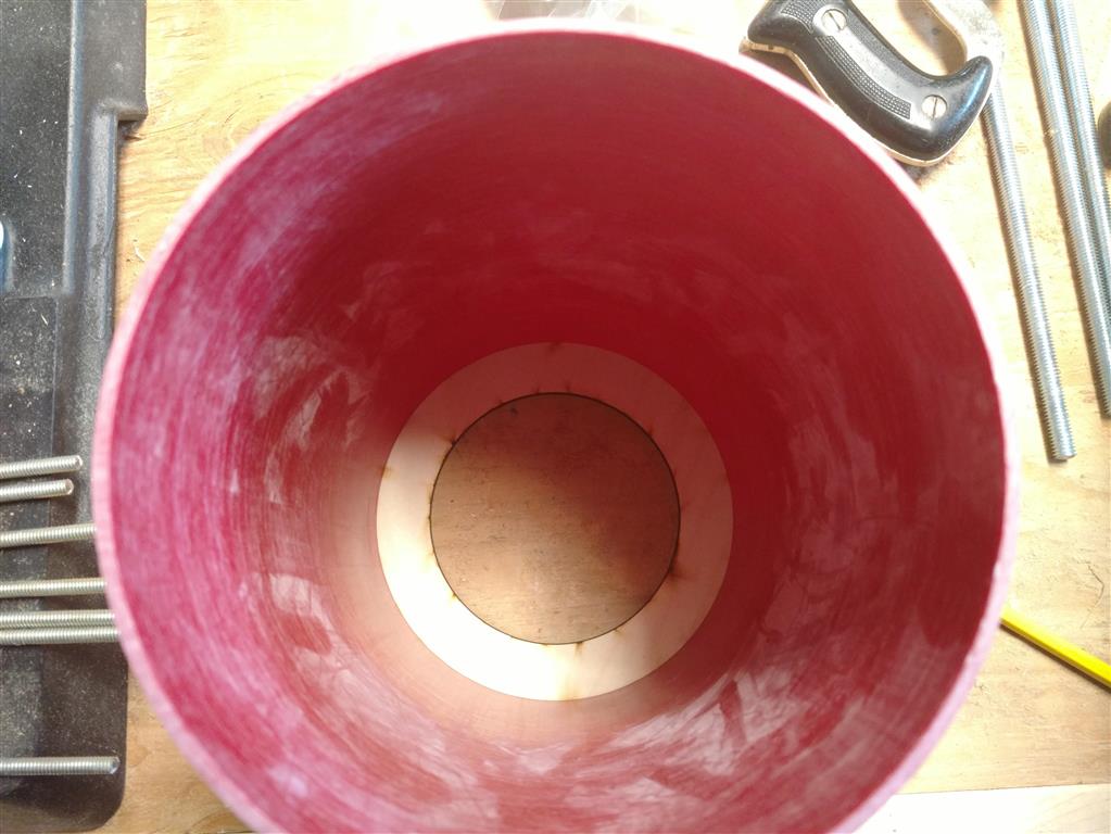
Since the wooden centering rings did not fit inside the coupler as intended, they needed to be reduced in outside diameter. A coupler and small section of body tube were used to hold the centering ring in place.

Here is the centering ring inside the body tube with the coupler set on top of it.

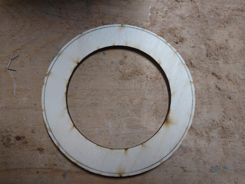
The inside diameter of the coupler was traced onto the centering ring with a sharp pencil, making sure to draw as close to the inner edge of the coupler as possible.

This is the upper wooden centering ring with the coupler's inside diameter drawn onto it.

This is the central wooden centering ring with the coupler's inside diameter drawn onto it.

The centering rings were sanded down to the correct outside diameter using the disk sander.

After the parts were ready, the fins were reinstalled into the fin mounts and all of the hardware installed.

The fin mounts and fins with all of their hardware.

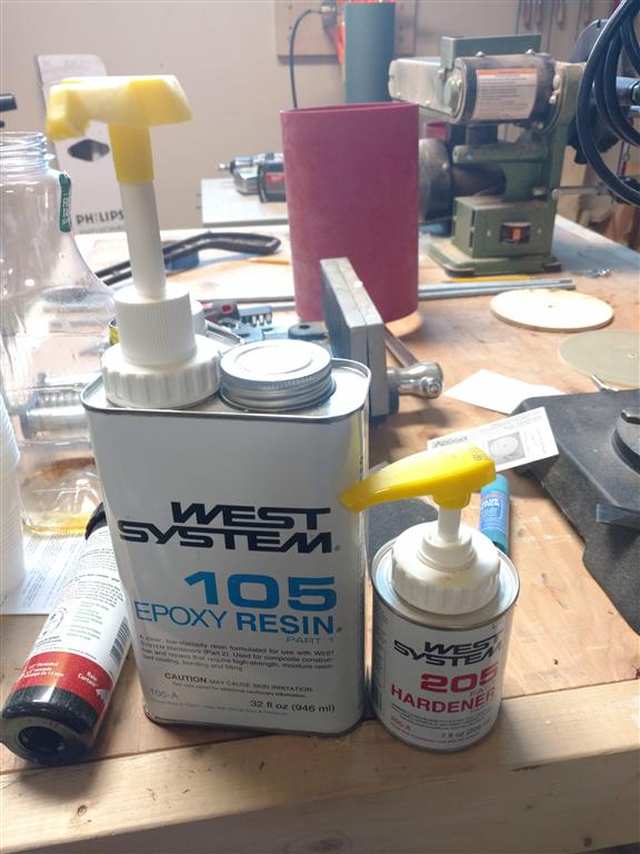
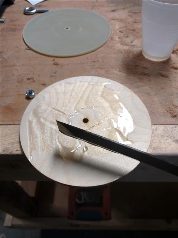
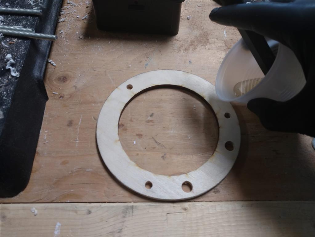
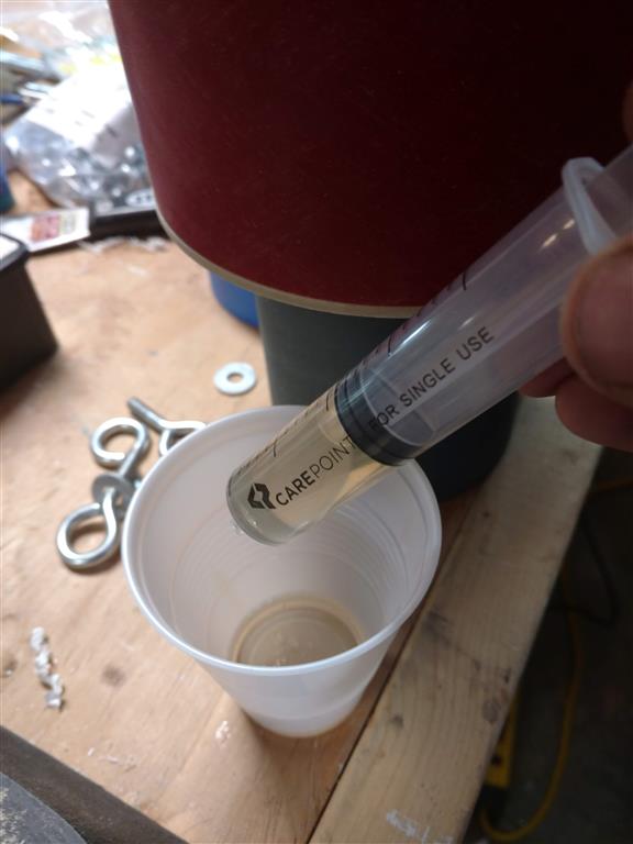
The fiberglass centering rings were epoxied onto their mating wooden rings using West Systems 105/205 resin and hardener. The epoxy was spread out evenly over the centering ring before putting the wooden ring onto it.

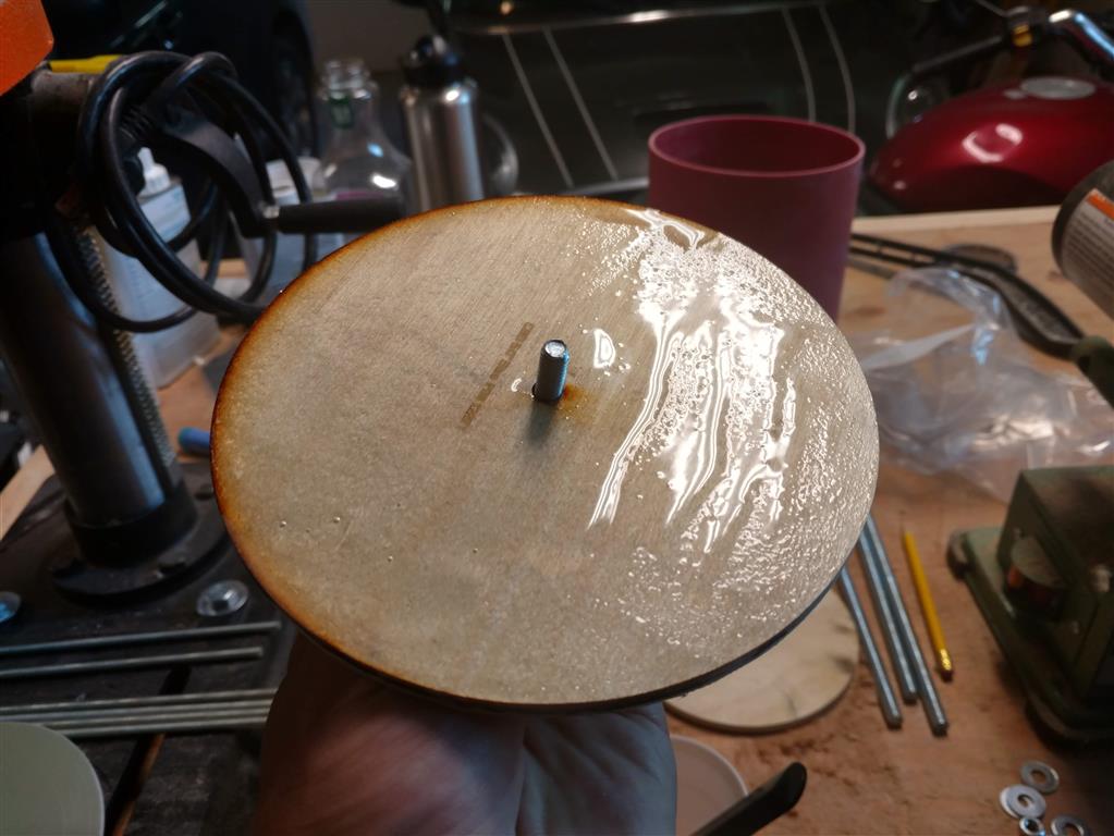
A scrap piece of motor mount tube was placed inside the centering ring before the wooden centering rings were placed onto the epoxy. Bolts were tightened through holes to both apply pressure and keep the holes lined up while the epoxy cured. The scrap pieces of motor mount tube were removed before the epoxy fully set.

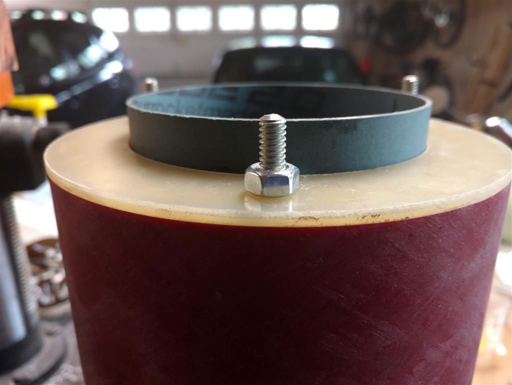
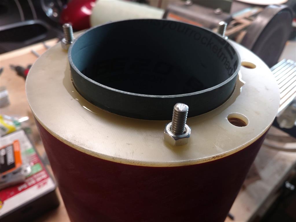
The window was set in place and central centering ring was set on top of it. Three bolts were but through the remaining holes in the centering rings and bulkheads and nuts tightened from below.

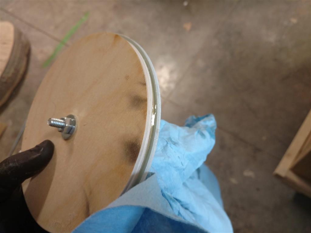
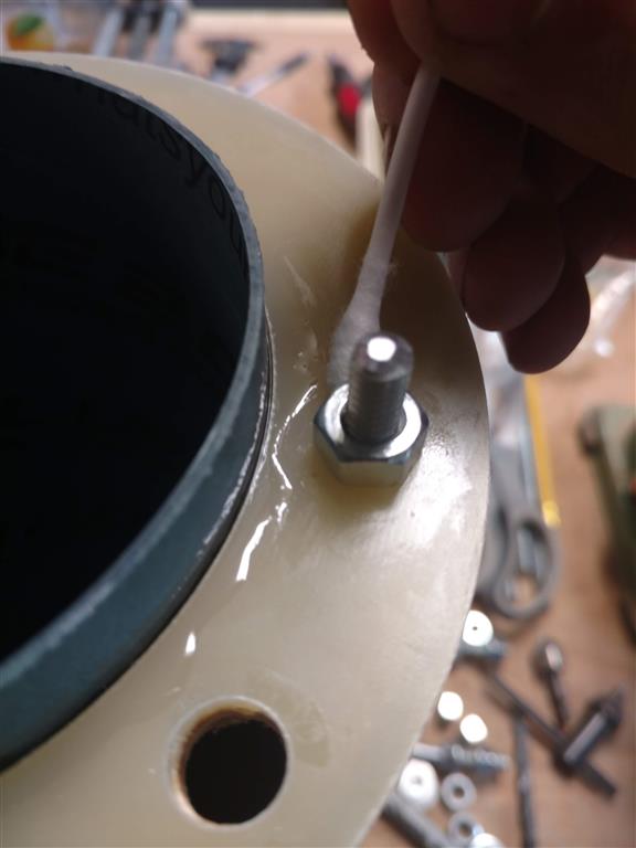
Locking nuts were put onto the bottom sections of the threaded rods to ensure that the rods did not move while the upper hardware was being tightened.

The upper coupler was slid onto the central wooden centering ring and then the upper centering ring, with the U-bolt installed, was placed onto the threaded rods and into the coupler. Nuts were tightened on the top of the upper centering ring to hold the assembly together. A scrap piece of body tube was then placed over the coupler to test the fit.

To ensure that the window and lower fiberglass centering ring would still fit inside the body tube, the fin can section's body tube was installed over the entire assembled inner section, stopping on the top surface of the fins.

The drill jig that was designed to ensure that the screw holes are at the correct positions.
Electronics Bay


Nosecone and Drogue Parachute Bay


Build Photos