The design of this rocket is entirely of my own design and was not based on any existing rocket or kit. All of the dimensions and features were chosen in an attempt to achieve the goals stated in post titled Level 3 Certification Rocket Design Goals.
Features and Dimensions
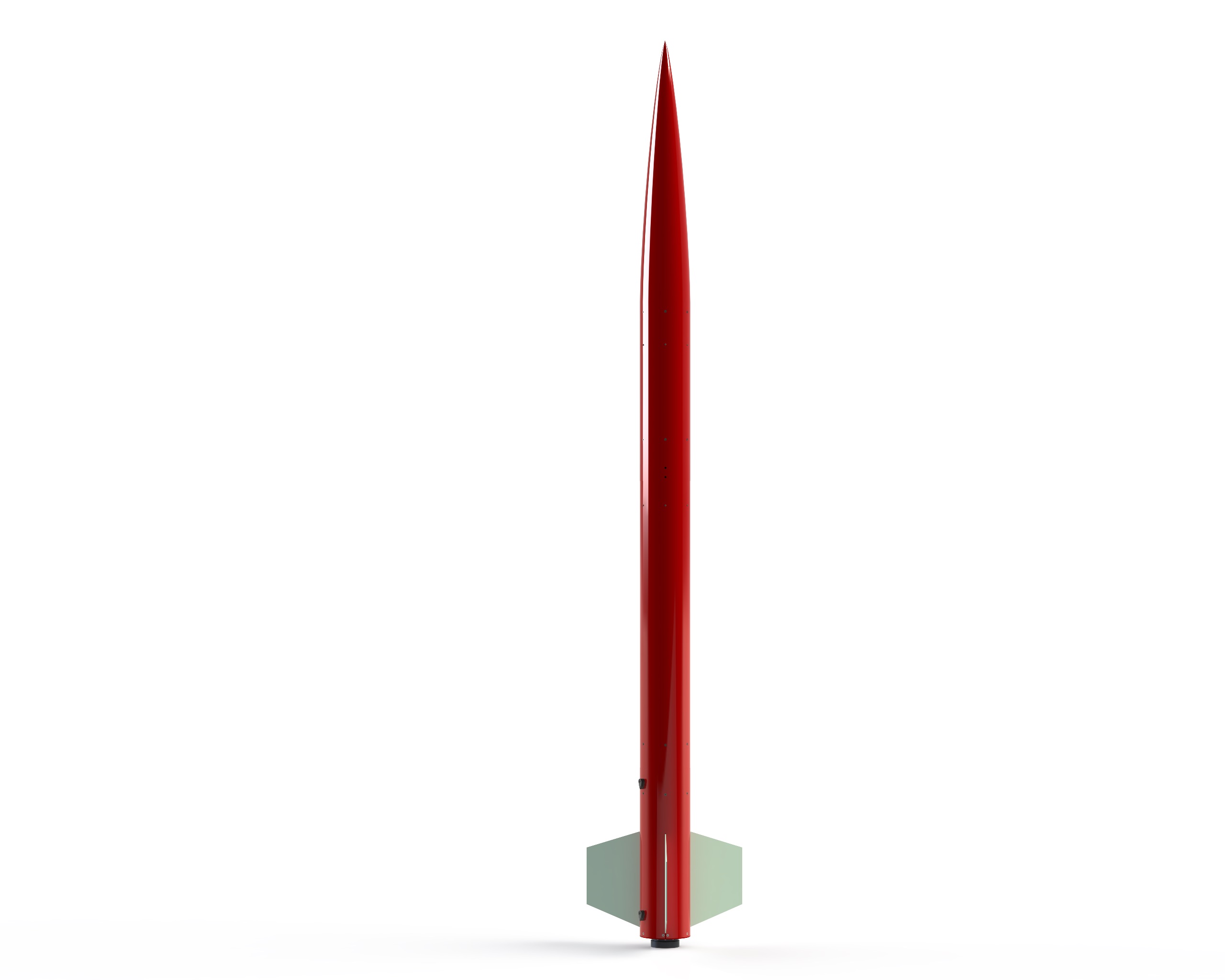
- 110.5in (2.807m) tall
- 6.17in (157mm) outside diameter, 6.0in (152mm) inside diameter, G10 fiberglass airframe tubes
- Center of pressure 87.3in (2.217m) down from tip of nosecone
- When loaded with Aerotech DMS M1350W:
- Center of mass 77.1in (1.958m) down from tip of nosecone
- Total launch weight of 55.0lb (244.7N) for an average thrust to weight of 5.52:1
- 3 G10 fiberglass fins, 0.125in (3.18mm) thick and custom trapezoidal shape
- 75mm motor mount
- Predicted weight of 44.41lbs (197.5N) without motor
- Five major subassemblies:
- Fin can section
- Main parachute bay
- Electronics bay
- Upper body tube
- Nosecone and drogue parachute bay
Key Differences from Preliminary Design
- Body Tubes: G10 fiberglass body tubes replaced the fiberglass wrapped phenolic body tubes from the preliminary design. This was done for several reasons. First, since flat head screws were desired to fasten the subassemblies together, it was desirable to have a single layer material to drill the necessary tapered holes into. This alleviated the risk of the fiberglass becoming delaminated from phenolic tubing underneath. Second, solid G10 fiberglass body tubes are actually cheaper per unit length compared to wrapped phenolic tubing. Finally, since both the nosecone and the fins are fiberglass, having a consistent material to paint should make the painting process simpler.
- Fin Size and Shape: The fins selected during the preliminary design phase (Public Missles FIN-D-05) would not withstand the speeds that the rocket is predicted to achieve without flutter. Therefore, a new geometry was needed. The shape of the fins was selected due the fact that the equations for predicting trapezoidal critical flutter speeds are readily available and their accuracy has been proven by many other people. Also, the shape of the fins is similar to the design that was used on my Tripoli Level 2 certification rocket, BigEZ.
- Elimination of the Tailcone: In order to make fabrication of the motor retention system simpler, the wooden tailcone was replaced with an aluminum thrust plate. This thrust plate is much stronger than the structure and should also be much less prone to damage. It also will allow for more frequent disassembly of the fin can section without risking damaging any of the tapped holes used for securing the motor retainer, fin can body tube or the threaded rods used for keeping the assembly together and bearing the loads exerted on the lower airframe by the main parachute.
- Von Karman Style Nosecone with Integrated Drogue Parachute Bay: In order to reduce the overall size and cost of the airframe, the rounded tip ogive style nosecone from the preliminary design was replaced with the 5.5:1 Von Karman style nosecone. The large volume of the new nosecone enabled the drogue parachute bay to be integrated into the nosecone. This eliminated about 18in (457mm) of tubing from the airframe. It also had the added benefit of reducing the total volume that needs to be pressurized by the black powder charge to eject the parachute.
- Integrated Camera Bay inside Fin Can Section: The original design had a combined electronics and camera bay that was very large. This resulted in the entire vehicle needing to be 28in (711mm) taller than the final design just to accommodate a the addition of small camera, such as a Go Pro. Also, in order to improve the video, it was determined that it would be best if the camera bay was not ejected by the parachute charges. Moving the camera bay lower in the vehicle allows for the camera to stay in the proper orientation throughout all phases of flight. The Go Pro camera was also replaced with a Raspberry Pi Zero W and Pi Camera. This setup was chosen to reduce the size of the window required for the camera and to enable the possibility of overlaying the video captured with real-time flight data from the dual-deployment avionics.
- Weight: The preliminary design had an estimated weight of 30.5lbs (135.7N) without a motor installed. The final design is significantly heavier at 44.41lbs (197.5N). This increase is primarily driven by having a much more complete model. The preliminary model did not account for the weight of all of the hardware (screws, nuts, washers, etc.), the U-bolts used as shock cord anchors the misc. components that are used with the parachutes (swivels, quick links, or parachute protectors). All of these small components make up a much larger portion of the vehicle’s weight than was originally predicted.
Rocket Section Separation In Flight
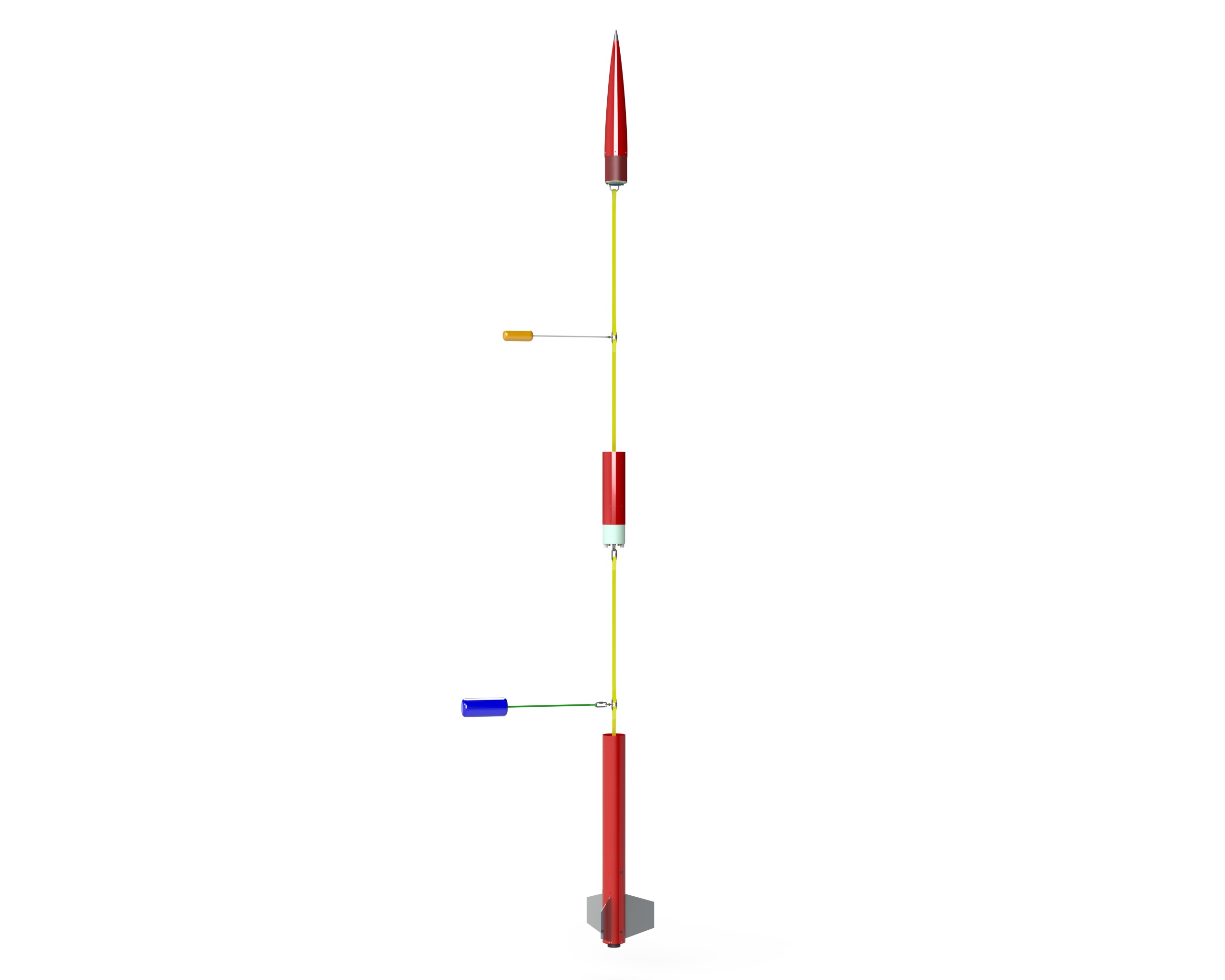
The rocket is design to separate into three sections during flight. Each section is connected via a pair of shock cords, connected serially, with the parachutes connecting to the shock cords where the cords come together. In the rendering above, the upper section is the nosecone and drogue parachute bay. The small object to the left of the main column in between the upper and middle sections, is the drogue parachute. (Please note, the lengths of the shock cords and parachute cords are not to scale.) The central section consists of the upper body tube and electronics bay. The object to the left in between the lower two sections is the main parachute. The bottom section consists of the main parachute bay and fin can section.
Individual drawings showing each of the general dimensions of the subassemblies can be found in the table below.